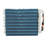
|
Specifications of condenser and evaporator coils |
||||
|
NO |
Tube Diameter(mm) |
Distance of hole/row(mm) |
Fin Style |
Fin Space(mm) |
|
1 |
Φ7 |
21*12.7 |
Louvered fin,Plain fin,Sine wave fin |
1.4~2.0 |
|
2 |
Φ7 |
21*18.9 |
Sine wave fin,Corrugated fin |
1.3~1.9 |
|
3 |
Φ7 |
25*21.65 |
Louvered fin |
1.5~3.8 |
|
4 |
Φ9.52 |
25.4*22 |
Louvered fin,Sine wave fin |
1.6~6.35 |
|
5 |
Φ9.52 |
25.4*22 |
Louverd fin,Plain fin,Sine wave fin |
1.6~3.2 |
|
6 |
Φ9.52 |
25*19 |
Louverd fin,Plain fin,Sine wave fin |
1.4~3.2 |
|
7 |
Φ9.52 |
25*21.65 |
Louvered fin,V ripple fin |
2.0~3.8 |
|
8 |
Φ9.52 |
25*25 |
Plain fin |
1.6~3.2 |
|
9 |
Φ9.52 |
25*21.65 |
Plain fin |
2.0~6.0 |
|
10 |
Φ9.52 |
25.4*22 |
Louvered fin,Plain fin,Sine wave fin |
1.6~6.35 |
|
11 |
Φ9.52 |
31.75*27.5 |
Louvered fin,Plain fin,Sine wave fin |
1.6~6.35 |
|
12 |
Φ12.7 |
31.75*27.5 |
Plain fin,Sine wave fin,V ripple fin |
1.8~6.0 |
|
13 |
Φ12.7 |
31.75*27.5 |
Louvered fin,Plain fin,Sine wave fin,V ripple fin |
1.7~2.2 |
|
14 |
Φ12.7 |
31.75*27.5 |
corrugated fin |
1.6~2.9 |
|
15 |
Φ15.88 |
38.1*33 |
Plain fin,Sine wave fin,V ripple fin |
2~4 |
|
1.5~4.1 |
1.5~4.2 |
1.5~4.3 |
1.5~4.4 |
1.5~4.5 |
We can serve for more types of evaporator according to every customers' drawing and requirement
|
|
Series 1 |
Series 2 |
Series 3 |
Series 4 |
|
Tube Diameter |
Φ 9.52 |
Φ9.52 |
Φ7 |
Φ 7.94 |
|
Hole Space(mm) |
25 |
25.4 |
20.5 |
22 |
|
Row Space(mm) |
21.65 |
22 |
12.7 |
19.05 |
|
Tube Material |
Copper, Aluminum |
Copper, Aluminum |
Copper, Aluminum |
Copper, Aluminum |
|
Type of Tube |
Smooth Tube |
Smooth Tube |
Smooth Tube |
Smooth Tube |
|
Fin Surface |
Louver Fin |
Flat Fin |
Flat Fin |
Louver Fin |
|
Fin Type |
Hydrophilic Foil |
Hydrophilic Foil |
Hydrophilic Foil |
Hydrophilic Foil |
|
Fin Thickness(mm) |
0.095~0.2 |
0.095~0.2 |
0.095~0.2 |
0.095~0.2 |
|
Fin Space(mm) |
1.4~2.3 mm |
1.4~2.3 mm |
1.1~1.8mm |
1.4~2.0 mm |

High-Efficiency Heat Exchangers for Combined Heat and Power (CHP) Systems
In power generation and industrial energy systems, maximizing thermal efficiency is critical. Sail Heat Exchanger designs and manufactures heavy-duty Waste Heat Recovery Exchangers specifically engineered for Combined Heat and Power (CHP) systems, cogeneration plants, and industrial boilers.
Our systems capture high-temperature waste heat from exhaust flue gases, steam, or jacket water, transferring it back into the production cycle or district heating networks, significantly reducing fuel consumption and carbon emissions.
Engineered for Harsh Power Plant Environments:
High-Temperature Optimization: Capable of withstanding extreme thermal stress and exhaust gas temperatures up to $550^\circ\text{C}$ to $600^\circ\text{C}$ without structural degradation.
Advanced Corrosion & Fouling Resistance: Available with heavy-wall stainless steel (316L/310S), corten steel, or specialized anti-fouling coatings to resist sulfur corrosion and ash accumulation from flue gases.
Custom Thermodynamic Design: Our engineering team utilizes advanced thermal simulation software to custom-configure tube bundles, fin pitches, and shell structures based on your specific flow rates and pressure drop requirements.


| Parameter Item | Heavy-Duty Power System Standard | Custom Capability Range |
| Primary Applications | Cogeneration (CHP) Units, Boiler Economizers | Exhaust Gas Heat Recovery, District Heating |
| Core Materials | Stainless Steel 316L, 304, Carbon Steel | Corten Steel, Inconel, Titanium |
| Max Operating Temp | Up to $450^\circ\text{C}$ | Up to $650^\circ\text{C}$ (High-Temp Alloys) |
| Design Pressure | $1.6\text{ MPa} - 4.0\text{ MPa}$ | Customized up to $10.0\text{ MPa}$ |
| Fin Type Options | Laser-welded Fin Tubes, H-Fins, High-Frequency Welded | Spiral Fins, Plate-fin configurations |
| Compliance Standards | ISO9001:2015, CE | ASME Code Section VIII (On Demand) |
Our Advantages
-
Looking for a Custom Thermal Design for Your Power System?
To help our engineering team provide an accurate thermal calculation and 3D drawing, please provide the following parameters when sending your inquiry:
Hot Side Medium: (e.g., Flue Gas, Clean Steam, Engine Exhaust)
Inlet & Outlet Temperatures: (C)
Mass Flow Rate: (kg/h or m^3/th)
Allowable Pressure Drop: (kPa)
Installation Space Restrictions: (If any)
Packaging & Shipping
The normal package is wooden box. If export to european countries, the wooden box will be fumigated. If container is too tighter, we will use pe film for packing or pack it according to customers special request.
lead Time
20 - 40 days
Payment Terms
50% T/T payment in advance, 50% T/T payment before delivery
Packing Condition
Standard export packing or customized packaging
Hot Tags: heat and power system heat exchanger, China heat and power system heat exchanger manufacturers, suppliers, factory, condenser water heat exchanger, Ice Maker Condenser Coils, new heat exchanger, refrigeration heat exchanger, heat exchanger units, heat exchanger and chiller